Markup Results
1Data Gateway uses a standard output to report rule violations, also known as non-conformances. This standard output (described below), referred to as Markup, provides information that enables a user to link reported non-conformances to individual non-conforming features in the submitted input dataset.
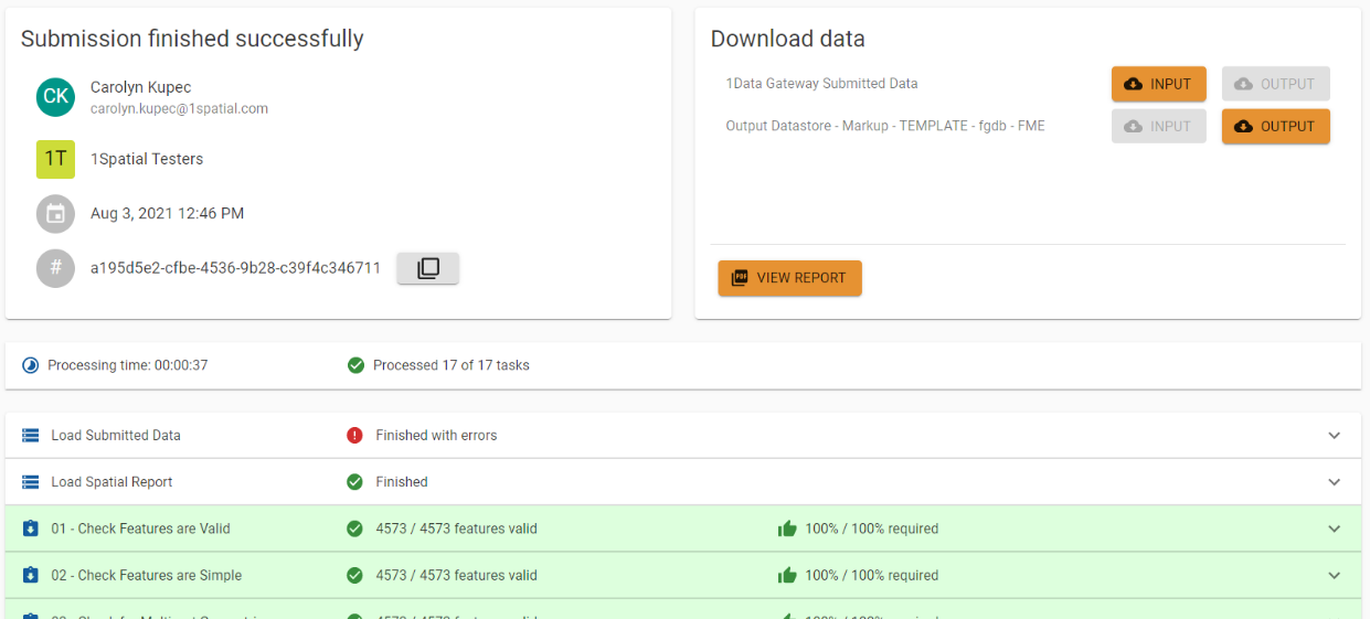
Download Output from 1Data Gateway
After a submission has finished successfully in 1Data Gateway, the output can be downloaded for review. Output data is downloaded as a compressed file and will contain an Esri File Geodatabase. To download this data, navigate to a Submission’s results page and look for an active Output button under the Download Data section on the right side of the screen.
Output File Format
Esri File Geodatabase
Reviewing Markup Results
After downloading and extracting the output dataset, the output files can be added to geospatial software. If viewing the output results with the input data, it is recommended to add the input data first, then add the output data to the same viewer as the input data.
Markup Results Schema
During the validation process, if the input data does not conform to the validation, output data is generated for that feature. The following schema and layers may be generated during the validation to represent non-conforming data.
 Markup Layers
Some output results will contain all of the Markup layers listed in Table 1, while other output results will only have applicable Markup layers. Attributes for each Markup layer are listed in the next section.
Table 1. Description of output markup layers.
|
Layer Name |
Description |
|---|---|
|
Markup_Area |
Class to hold instances where returning an area geometry provides the most value for detailing a non-conformance. 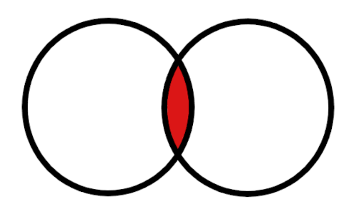
|
|
Markup_Line |
Class to hold instances where returning a linear geometry provides the most value for detailing a non-conformance. 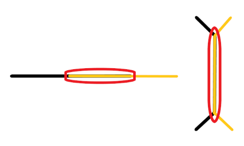
|
|
Markup_Point |
Class to hold instances where returning a point geometry provides the most value for detailing a non-conformance. 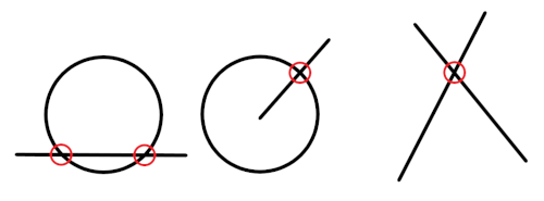
|
|
Markup_Table |
Table (nonspatial) to hold instances where the data being processed and reported is either non-spatial in nature, or when a feature has null or invalid geometry (as defined by the Open Geospatial Consortium definition of valid geometries). |
|
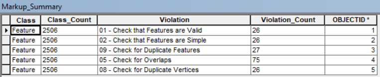
Markup_Summary |
Table (nonspatial) presenting a summary of Rule Violations aggregated by layer and providing a count of occurrences. |
|
Markup_Fishbone |
A special case linear Markup, used to show a calculated proportional linkage between a point feature (e.g. address point or asset object) and a linear route feature (e.g. a Road Centerline or a measured Route line). 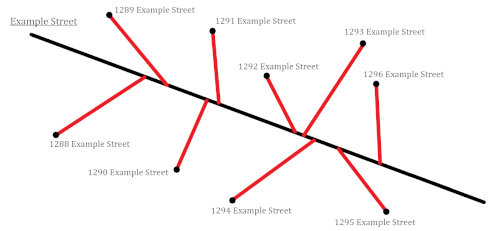
|
Markup Layer Attributes
Markup_Area, Markup_Line, Markup_Point, Markup_Table Attributes
There are four attributes that are found in the following Markup classes: Markup_Area, Markup_Line, Markup_Point, and Markup_Table.
Table 2. Attributes in the Markup_Area, Markup_Line, Markup_Point, and Markup_Table layer classes.
|
Attribute Name |
Field Type |
Description |
|
Class* |
String |
The input class to which the Markup is associated |
|
Violation* |
String |
The name of the rule violated |
|
Comment |
String |
Additional information about the rule violation |
|
Feat_ID* |
String |
The associated input feature’s unique identifier |
|
*Denotes an attribute that is provided at a minimum for a Markup feature. |
||
The information provided in a Markup record minimally includes the input layer the feature is associated with, the ID of the non-conforming input feature, and the rule that the feature failed. Sometimes, additional information is provided, including a comment providing more detail as to how/why the feature failed the rule, a severity value of the rule violation (e.g., low, moderate, critical), and/or a confidence score.
Markup_Summary Attributes
The Markup_Summary table presents a summary of rule violations (non-conformances) found across each of the Markup layers.
Table 3. Attributes found in Markup_Summary.
|
Attribute Name |
Field Type |
Description |
|
Class |
String |
The input class to which the Markup is associated |
|
Class_Count |
String |
Total number of features in the class/feature layer |
|
Violation |
String |
The name of the rule violated |
|
Violation_Count |
String |
Total count of non-conformances for a violated rule |
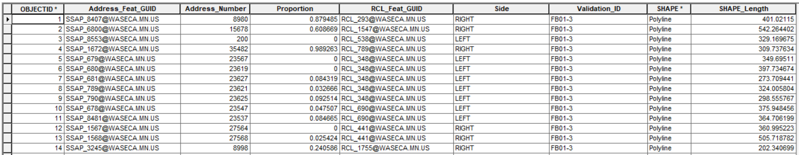
Markup_Fishbone Attributes
A special case linear Markup, the Markup_Fishbone layer is used to show a calculated proportional linkage between a point feature (e.g. address point or asset object) and its interpolated correlating position along a linear route feature (e.g. a Road Centerline or a measured Route line).
Table 4. Attributes found in Markup_Fishbone layer.
|
Attribute Name |
Field Type |
Description |
|---|---|---|
|
Address_Feat_GUID |
String |
Associated address point feature unique identifier |
|
Address_Number |
Integer |
Address number of the point feature |
|
Address_Number_Prefix |
String |
Address number prefix of the address point feature. This field is only populated if the corresponding input data is populated and mapped at time of schema mapping. |
|
Address_Number_Suffix |
String |
Address number suffix of the address point feature. This field is only populated if the corresponding input data is populated and mapped at time of schema mapping. |
|
Proportion |
String |
Value of the address number’s proportional distance along the matching road centerline using the road address range and length |
|
RCL_Feat_GUID |
String |
Associated road centerline unique identifier |
|
Side |
String |
The side of the road a fishbone is on, based on the road centerline’s digitization direction Values: LEFT RIGHT |
|
Validation_ID |
String |
The name of the rule violated |