A project can contain a series of styles for different purposes, however only one can be used (the current style) to display the data in the main map window at any one time.
To create and edit styles, select Style from the lower app bar.
To select the current style, right-click in the Style page select a style from the icons at the top of the page. For example:
![]()
To rename a style, click on the name in the icon and enter a (unique) new name.
You can specify colours and text that will be used to display features on the map, use background raster layers, and specify which feature types will be displayed on the map. Styles can also be created, exported, and imported for use with other projects.
A style is made up of a series of ordered layers, and these layers are seen in the Styles page. The layers are displayed from the bottom layer upwards. A layer can be used to display a vector geometry, a raster file, or text based on a vector geometry. You can have multiple layers that reference the same feature.
You can create a style, then import or export the style for use with other projects. To create, load, or export a style, right-click on the Style page. From here, you can:
· Create
a style: Click Create and enter
a name for the style. Click Ok.
Define styles as required, and click ![]() to save the new style template. A newly created style is always automatically
selected as the current style.
to save the new style template. A newly created style is always automatically
selected as the current style.
· Import a style: Click Import Style and select a .style file, then click Open.
· Export a style: Click Export Style and enter a name for the style file, then click Save.
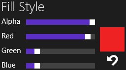
Click on the feature type and enter the values for styles you want to change. To change the colour of a feature's fill, stroke, or point style, use the colour sliders to change the RGB values. To change the opacity of the colour, use the Alpha slider. For example:
Click ![]() to
add a feature type to the Style list. The Select
Classes page is displayed, where you can select a class to add
to the list. To display secondary geometries, add a vector layer. When
you add a vector layer, you can select which geometry to draw for the
layer. To display more than one geometry of a feature, add vector layers
for each geometry.
to
add a feature type to the Style list. The Select
Classes page is displayed, where you can select a class to add
to the list. To display secondary geometries, add a vector layer. When
you add a vector layer, you can select which geometry to draw for the
layer. To display more than one geometry of a feature, add vector layers
for each geometry.
Click ![]() to specify
text attributes for a specific class. The Select Classes page is displayed,
where you can select a class to add to the list.
to specify
text attributes for a specific class. The Select Classes page is displayed,
where you can select a class to add to the list.
Click ![]() to finish
adding the class(es) and return to the Style page, then select the class.
The text options are displayed for the selected class:
to finish
adding the class(es) and return to the Style page, then select the class.
The text options are displayed for the selected class:
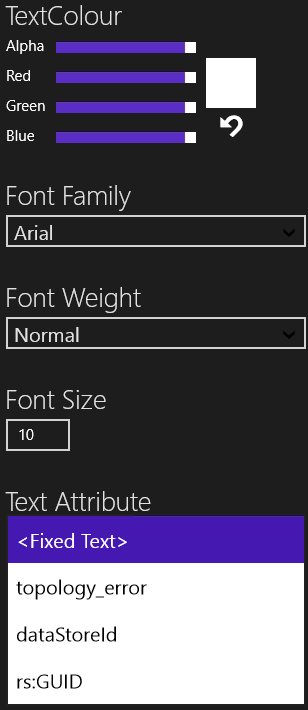
Use the colour sliders to adjust the text colour, select a font style from the Font Family list, enter a font weight and size, and select the type of text you want to display from the Text Attribute list. You can specify the text attribute, which is either a read-only fixed text value, or the value from one of the string properties.
Drag and drop feature layers in the style list to determine in what order specific layers appear on the map.
Click ![]() to add a raster image background to the
map. Navigate to the file you want to use, select it, and click Open. Only GeoTiff files that are
in the same SRID as the vector data are shown. Adjust the Opacity
if required.
to add a raster image background to the
map. Navigate to the file you want to use, select it, and click Open. Only GeoTiff files that are
in the same SRID as the vector data are shown. Adjust the Opacity
if required.
There can only be one raster layer in a style; however, that raster layer can contain many GeoTiff files. You can add and remove files from this single layer.
The list of GeoTiff files is shared by all layers. If there is more than one layer with a raster style, both of those styles will share the same list of files.
Click ![]() to finish adding
the class(es) and return to the Style page.
to finish adding
the class(es) and return to the Style page.
To remove a feature type from the Style list, select it and click Remove. The feature will no longer be displayed on the map, but can be added back again by selecting Add from the Style page.
Click ![]() to add a thematic layer to draw features
in a class with a symbology that depends on the value of a property in
that class. Select a class, select Configure
and select which geometry (if applicable) on the Thematic
Layer page. From the drop-down list, select a property. For each
different property value that requires a different symbology, click Add Rule. A rule allows the user
to define a property value and the symbology to use when drawing features
whose property equals the specified property value. Configure the symbology
that should be used when drawing features with that property or click
Default Rule to configure a default
theme for any remaining properties in that class. If there is a default
rule, any features that are not identified by any other rule will be drawn
in the default rule style, otherwise these features will not be drawn
(but are still selectable.)
to add a thematic layer to draw features
in a class with a symbology that depends on the value of a property in
that class. Select a class, select Configure
and select which geometry (if applicable) on the Thematic
Layer page. From the drop-down list, select a property. For each
different property value that requires a different symbology, click Add Rule. A rule allows the user
to define a property value and the symbology to use when drawing features
whose property equals the specified property value. Configure the symbology
that should be used when drawing features with that property or click
Default Rule to configure a default
theme for any remaining properties in that class. If there is a default
rule, any features that are not identified by any other rule will be drawn
in the default rule style, otherwise these features will not be drawn
(but are still selectable.)
To delete the current style, click Delete Current.