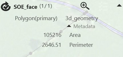
When you select a feature on the map, its attributes and the number of currently selected features are displayed in the Properties panel:
You can expand and collapse the panel using the arrows at the top of
the panel. Click ![]() to
collapse the panel. When the menu is collapsed, the top line of the properties
panel is still visible so that you can see the class of the selected feature
and access the buttons, but properties are not displayed so that the map
is not obscured. To zoom in on the selected feature, use
to
collapse the panel. When the menu is collapsed, the top line of the properties
panel is still visible so that you can see the class of the selected feature
and access the buttons, but properties are not displayed so that the map
is not obscured. To zoom in on the selected feature, use ![]()
Some properties can be edited by either clicking to enter new values or selecting new values from drop-down menus. Metadata can be viewed by clicking + to expand the text. Metadata is properties that provide information about other properties. Any property that is of the form propertyId or propertyValue will be assumed to have metadata properties if they have the name that starts with property.
Feature references are displayed like hyperlinks: click on the link to select the referenced feature. For attributes that are references to single features, use - to remove the reference and + to allow you to specify the feature that is referenced by selecting it from the map. For attributes that are references to multiple features, use - to remove a reference and + to add a reference by selecting a feature on the map. You can expand and collapse this list of references.
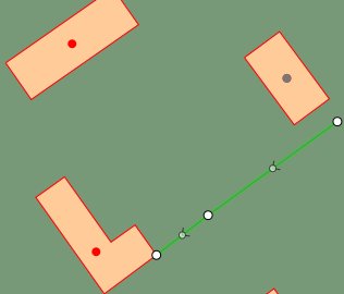
The direction of existing lines and vectors and features you digitise are indicated by arrows on the map. For example:
By default, single selection mode is enabled. Click or tap on the map to select a feature. When you select a feature, any selected features are deselected first.
Click ![]() in the Context
bar to clear the selection, or click the selected feature to deselect
it.
in the Context
bar to clear the selection, or click the selected feature to deselect
it.
When you tap at a location to select, a priority is applied. Points at that location are selected ahead of lines, which are then selected ahead of polygons. If you tap on a point feature on a line feature that runs along the boundary of an area, the point is selected first. If there is a possible ambiguity at the location you tapped (for example, if there are two features of equally high priority), a pop-up menu is displayed to allow you to select the feature.
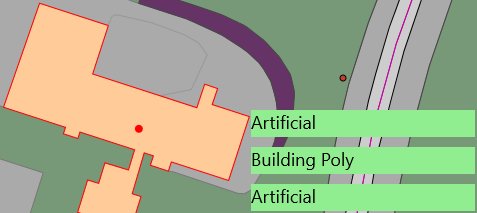
Features are selected if they are within snapping tolerance of the click location. Tolerance is defied in the 1Edit Settings panel. In the following example, there are two Artificial polygons and one Building Poly polygon that are within snapping tolerance of the clicked point. Tap Artificial on the menu to select that feature. If the feature that you want to select overlaps or is underneath another feature, click on it and select it from the classes displayed in the pop-up menu. For example, click Artificial to select that polygon:
In some data models, a feature class will be defined to allow it to have multiple geometries. In such models, there will always be one primary geometry and possible many ancillary (secondary) geometries. For example, a Building feature may have a primary geometry that is a polygon representing the building outline and a secondary geometry representing a seed point within the building. The secondaries do not need to be within the primary geometry.
Only primary geometries can be added to a topology. When adding a layer in the style page, you specify which of the geometries to display for the layer. To display more than one geometry from a feature, you need a separate layer for each geometry.
For features with more than one geometry, you must click on the primary geometry to select the feature, the secondary geometries are not directly selectable. If you need to access the secondary geometries (for example, to digitise one), then you need to enable the Support Secondary Geometries option under 1Edit Settings on the Charms menu. When this mode is enabled, when you select on a feature’s primary geometry, a pop-up menu is displayed to allow selection of the primary or secondary geometries:
In this example, the primary of the Way class is a polygon and it can hold a secondary geometry in the lineGeomValue attribute. If there is no geometry in the attribute, it is shown faded but can still be selected. This is used to indicate to the system that the user wishes to digitise a geometry into the secondary geometry. After selecting the empty secondary geometry, the digitising class on the Create data bar is set to that of the selected feature and it shows which geometry you are about to digitise into:
You can now use the digitising tools to digitise the secondary (in this case, select the digitise line tool and digitise the new line). If you select the secondary in error, de-select the feature to clear. You must set up a style that shows the secondary geometries to see them after digitising.
A style layer will add the class's primary geometry by default, however, you can select a different class for a layer. Add a layer for each of the class's geometries that you want to display.
If the secondary geometry contains a geometry, the entry in the pop-up menu is not faded and tapping on the entry selects and highlights the secondary. You can now drag vertices and so on as for primary geometries to edit the shape of the geometry, and dragging the geometry off the screen (or using the delete appbar button) clears that secondary geometry, as opposed to deleting the feature. When the secondary is empty, the digitising class is changed to indicate a secondary is selected and using one of the digitising tools, allows you to completely re-digitise the geometry from scratch.
For features with more than one geometry, you must click on the primary geometry to select any of the geometries of a feature. If a secondary geometry extends outside of the primary geometry, you can only select it by clicking inside the primary geometry first.
When you click on the primary geometry of a multi-geometry feature, both the primary and any secondary geometries are shown in the selection popup list. Click on the primary geometry (listed first) to select and edit the primary geometry of the feature. Click on a secondary geometry (listed, indented after the primary geometry) to select and edit that secondary geometry. If that secondary geometry of the feature is not yet defined, selecting it allows you to create the secondary geometry; you can then use the Create data bar to create the geometry for the selected feature.