Points can be added in a variety of ways with reference to existing features. These operations are normally used to generate construction points that are used to capture other features.
Before starting any of these digitising operations make sure that you have selected an appropriate Point feature class in Digitising class dropdown.
Note:You can also create points by simply digitising by clicking on the map (see Create a Point).
Point Along Line
Add a single point on or in line with an existing line feature or defined vector.
As you
add points, the tie out distance (distance remaining to the end point of the line or vector) is automatically
calculated and displayed in the panel.
Select the appropriate point feature class by clicking .
Select the line along which you want to add a point.
Click .
Select the end of the line from which the distance will be measured, by clicking it on the map.
Enter the Distance along the line at which to place the point, and specify a Height for the point.
If no height is specified it will be interpolated from the selected line.
Note:If the distance specified for the distance is negative, the point is placed on the
backward projection of the line’s first segment. If the distance is greater than
the length of the line, the point is created on the projection of the line’s last
segment.
Click Accept.
The point is created at the specified distance along the line.
Select the appropriate point feature class by clicking .
Click .
Digitize a vector on the map by clicking the start and end points of the vector.
Enter the Distance along the vector at which to place the point, and specify a Height for the point.
If no height is specified it will be interpolated from the selected line.
Note:If the distance specified for the distance is negative, the point is placed on the
backward projection of the vector. If the distance is greater than
the length of the line, the point is created on the projection of the vector.
Click Accept.
The point is created at the specified distance along the vector.
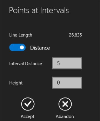
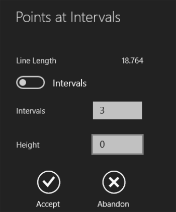
Points at Intervals
Create points at defined intervals along an existing line or a user-specified vector. You can define these either by the distance between points or by the number of intervals:
The Distance option is used to specify the distance between points along the line, starting at the start point of the line or vector. A point is placed at distance 0 and then regularly at distance along the line until the end of the line.
Note: A point is not placed at the endpoint of the line unless it is an exact multiple of distance.
This operation is generally used to lay out regularly spaced features such as telephone posts etc.
Intervals defined by distance
The Intervals option is used to define the number of intervals, and therefore spaces out points equally along a line. A point is created at the start and end point of the line and any other points are spaced out equally between these.
This operation is generally used to subdivide a line e.g. to place a construction point at the midpoint of the line you would specify 2 as the number of intervals. This would create 3 points, one at each end and one in the middle.
Select the appropriate point feature class by clicking .
Click .
Digitize a vector on the map by clicking the start and end points of the vector.
Use the toggle to select either the Intervals or Distance interval type.
Once selected, enter either the Interval Distance or number of Intervals, and specify a Height for the points.
If no height is specified it will be interpolated from the selected line.
Click Accept.
Points are created along the length of the vector line as specified above.
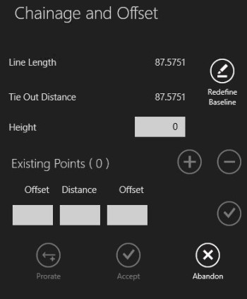
Chainage and Offset
Chainage and Offset can be used to create points by placing them certain distances and offsets along a line or vector.
As you add points, the tie out distance (distance remaining to the end point)
is automatically calculated and displayed in the panel alongside the total line length.
Select the line along which you want to add some points.
Click .
Select the end of the line from which you want the series of points to begin.
The Chainage and Offset panel is displayed.
Chainage and Offset panel
Enter the Distance along the line at which to place a point, and specify a Height for the point.
If no height is specified it will be interpolated from the selected line.
Note:If the distance specified for the distance is negative, the point is placed on the
backward projection of the line’s first segment. If the distance is greater than
the length of the line, the point is created on the projection of the line’s last
segment.
Enter a value in one of the Offset fields.
A value in the left-handOffset field creates
a point to the left of the line, and a value in the right-handOffset field creates
a point to the right of the line.
Note:By default, Offset values cannot be longer than half the length of the vector. This restriction can be overridden by changing the Limit Offset for Chain/Offset setting in the 1Edit settings panel.
To create a point along the line without an offset,
do not enter a value in either of the Offset fields.
Click to add the point.
Repeat steps 6 - 8 to place additional points.
Note:To edit a point in the series, select it from the list and enter new values. To delete a point in the series, select it and click . To then continue adding new points, click .
Note:You can reverse the direction of your series of points at any stage by clicking Redefine Baseline and clicking the other end of the selected line.
Digitize a vector on the map by clicking the start and end points of the vector.
The Chainage and Offset panel is displayed.
Chainage and Offset panel
Enter the Distance along the vector at which to place a point, and specify a Height for the point.
Note:If the distance specified for the distance is negative, the point is placed on the
backward projection of the vector. If the distance is greater than
the length of the line, the point is created on the projection of the vector.
Enter a value in one of the Offset fields.
A value in the left-handOffset field creates
a point to the left of the vector, and a value in the right-handOffset field creates
a point to the right of the vector.
Note:By default, Offset values cannot be longer than half the length of the vector. This restriction can be overridden by changing the Limit Offset for Chain/Offset setting in the 1Edit settings panel.
To create a point along the vector without an offset,
do not enter a value in either of the Offset fields.
Click to add the point.
Repeat steps 5 - 7 to place additional points.
Note:To edit a point in the series, select it from the list and enter new values. To delete a point in the series, select it and click . To then continue adding new points, click .
Note:You can re-define your vector at any stage by clicking Redefine Baseline and digitising a new vector. Your points will be saved.
Click Accept.
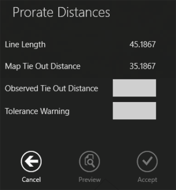
Prorating Distances
Prorating allows you to match calculations taken on the ground to the map, compensating
for any differences in calculations.
 .
. .
.
 .
. .
.
 .
. or polygon mode
  .
.