Dual Carriageway Group
In this group, 8 operations have been made available to collapse dual carriageways to centrelines. These are presented in a logical order to show the order in which they should be used to collapse the dual carriageways on the road network.
To use these operations, the system class representing target roads (usually named ROAD_TGT) need to have some attributes and references set. The attribute IS_COLLAPSIBLE is used by the process to ignore any roads which have this attribute set to false. The user can write their own action to initialise this parameter as they wish. For example, an action could be written to identify all roads which are part of a roundabout, and set their IS_COLLPSIBLE attribute to false.
Two references are defined. The first is IS_PAIRED_TO/IS_PAIRED_FROM which is used to store pairing candidates for each road. When candidates are first identified, a road can be paired with several candidates for each road. When candidates are first identified, a road can be paired with several candidates. The process will then try to enforce a 1 to 1 pairing, so that a centreline can be computed. The second reference IS_COLLAPSED TO/IS_COLLAPSED_FROM is used to link a centreline to its original roads. This is a 1 to many reference, a road can be collapsed to at most 1 centreline, but a centreline comes from 2 initial roads.
The xml below shows the schema definition for a ROAD_TGT class on which the dual carriageway collapse process can be used. The items which are specific to the collapse process are highlighted in red.
<Class name="ROAD_TGT">
<BaseClass name="PARTITIONING_TGT"/>
<Attribute minOccurs="1" maxOccurs="1" name="ID" datatype="String"/>
<Attribute minOccurs="1" maxOccurs="1" name="TYPE" datatype="String"/>
<Attribute minOccurs="1" maxOccurs="1" name="NEAR_PARTITION" datatype="Boolean"/>
<Attribute minOccurs="1" maxOccurs="1" name="IS_COLLAPSIBLE" datatype="Boolean"/>
<Attribute minOccurs="1" maxOccurs="1" name="MATCHED" datatype="Boolean"/>
<Attribute minOccurs="0" maxOccurs="unbounded" name="FK_ID" datatype="String"/>
<Attribute minOccurs="1" maxOccurs="1" name="FK_SINGLE_ID" datatype="String"/>
<ForeignKey name="IS_PAIRED_TO" referenceClass="ROAD_TGT" referenceKey="PK_ROAD_TGT"
reverse="IS_PAIRED_FROM">
<Attribute minOccurs="1" maxOccurs="1" name="FK_ID"/>
</ForeignKey>
<ForeignKey name="IS_PAIRED_FROM" referenceClass="ROAD_TGT" referenceKey="PK_ROAD_TGT"
reverse="IS_PAIRED_TO">
<Attribute minOccurs="1" maxOccurs="1" name="FK_ID"/>
</ForeignKey>
<ForeignKey name="IS_COLLAPSED_TO" referenceClass="ROAD_TGT" referenceKey="PK_ROAD_TGT"
reverse="IS_COLLAPSED_FROM">
<Attribute minOccurs="1" maxOccurs="1" name="FK_SINGLE_ID"/>
</ForeignKey>
<ForeignKey name="IS_COLLAPSED_FROM" referenceClass="ROAD_TGT"
referenceKey="PK_ROAD_TGT" reverse="IS_COLLAPSED_TO">
<Attribute minOccurs="1" maxOccurs="1" name="FK_ID"/>
</ForeignKey>
<UniqueKey name="PK_ROAD_TGT">
<Attribute minOccurs="1" maxOccurs="1" name="ID"/>
</UniqueKey>
</Class>
- ddc_identify_candidate_pairs
- Parameter 1 (Object): A road for which the search is for candidate pairs.
- Parameter 2 (String): A name of the Boolean attribute defined on the road class that indicates if the road is collapsible or not. Road objects which are not collapsible won't be considered for pairing.
- Parameter 3 (String): The name of the reference used to set direct links between paired roads.
- Parameter 4 (String): Pipe (|) separated list of attribute names. Roads can only be paired if these attributes match. This is typically used with attributes indicating the type/classifcation of the road or the name of the road.
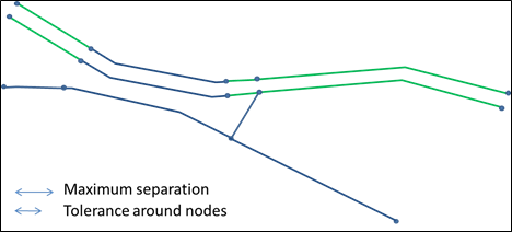
- Parameter 5 (Double): Maximum separation. Two roads which are distant (minimum distance) by more than this value (in data unit, usually meters) will not be paired.
- Parameter 6 (Double): Minimum length. Road B will only be considered a candidate for pairing with A, if there exists at least on continuous section of B which is fully within maximum separation (parameter 5) distance of, and whose length is greater or equal to this value.
This operation looks for candidates that could be paired to the road passed in parameter 1. The reference IS_PAIRED_TO is set to reference all the candidates for pairing this road to.
Example:
In this example Figure, we are looking for candidates to pair with the red road.
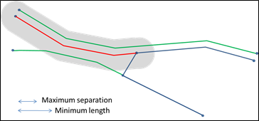
The red road to be paired
The grey area shows the area within Maximum Separation distance of that road. The two green roads are the candidates which have been identified. Two other roads intersect the grey area, but they do not get retained as candidates because the length of the section close enough to the red line is shorter that the Minimum Length. Minimum Length should always be greater than Maximum Separation to disqualify roads connected to the initial one at crossroads.
- dcc_split_candidate_pairs
- Parameter 1 (Object): The starting road.
- Parameter 2 (String): Name of the reference used to set direct links between paired roads.
- Parameter 3 (Double): Maximum separation. Paired roads will be split so that sections which are within Maximum Separation of the starting road are isolated.
- Parameter 4 (Double): Tolerance around nodes. A road will only be split if the new node is not closer than this tolerance from one of the nodes of that road before splitting. This is to avoid creating tiny road sections.
- Parameter 5 (String): Pipe (|) separated list of attribute names. When a road is split, creating two new road sections, these two objects have their attributes named in this list set to null.
This operation isolates the section of candidate pairs which are within the Maximum Separation distance. This is an important step in the process of retaining only 1 to 1 pairing references that can then be collapsed.
Example:
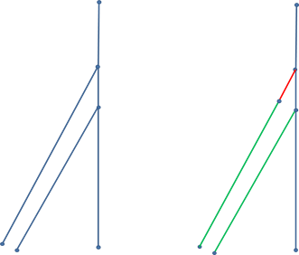
The Figure below shows the green roads being split when processing the red one.
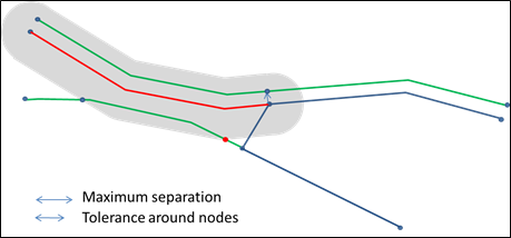
Roads being split.
It is worth noting that the red node is not retained (no split there), as it is within tolerance of the original end node of the green road which is being split. At the end of this process, all the pair candidates for the red road have been split into sections which are either within the pairing distance or not (after considering tolerances around nodes).
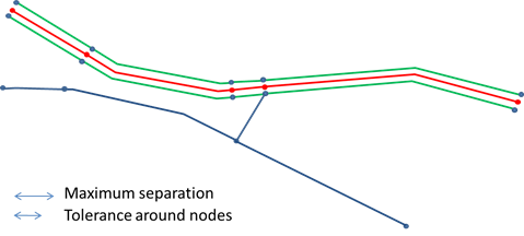
This is an iterative process, so all roads will be processed and their pairing candidates will be split. This means that when processing the bottom green line from the picture below, the red one will be split in three. The three parts will then be processed and cause the top road to be split as well.
The final result of this iterative process is shown below. The arrows are there to show where the new nodes come from.
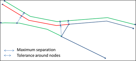
The results of the process
- dcc_filter_candidate_pairs
- Parameter 1 (Object): The road being processed.
- Parameter 2 (String): Name of the reference to potential paired roads.
- Parameter 3 (Double): Maximum separation. (See previous operation).
- Parameter 4 (Double): Tolerance around nodes (See previous operation).
This operation filters out some candidate pairs for the road being processed. Candidates remain if they are fully within Maximum Separation (parameter 3) distances from the road, and that any node projected on the paired road is within tolerance (parameter 4) of an end node from that paired road.
Example:
This Figure shows the remaining pair candidates (green) for the red road.
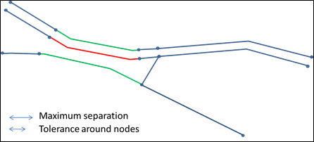
The pair candidates
- dcc_match_simple_pair
- Parameter 1 (Object): The road being processed.
- Parameter 2 (String): name of the reference to potential paired roads.
- Parameter 3 (String): Attribute name used to mark roads which are paired.
This operation marks all roads which have a single candidate pair, by setting up an attribute to true. The attribute used is the one specified by parameter 3. It must be declared in the system schema. At this stage, only pairs which can be identified without any ambiguity are marked.
Example:
The figure below identifies in green all of the roads which would be marked as paired at this stage.
Roads marked for pairing
- dcc_append_short_line
- Parameter 1 (Object): The road being processed.
- Parameter 2 (String): Name of the reference to potential paired roads.
- Parameter 3 (String): Attribute name used to mark roads which are paired.
- Parameter 4 (Double): Tolerance around nodes (see previous operation).
- Parameter 5 (Double): Maximum angle deviation (in degrees) between the short road and the paired road connected to it.
This operation aims at filling gaps that the earlier part of the process often leaves,this usually happens in cases similar to the next Figure. When a road crosses a dual carriageway with a sharp angle, one side of the dual carriageway is often split to offer a better match. This may leave a small road section without a match on the other side. To avoid leaving a gap, such roads are detected and a pairing is added with the opposite road, which ends up being paired to two roads.
Example:
In this figure, the bottom right green road is paired with both the other green and the red roads. All three roads have their attribute (parameter 3) set to true.
The roads are paired in that way only when they extend a paired road: they must be linked to it by a 2 arms node, and have an orientation at that node which varies from the other road by less than the value specified by parameter 5.
Short line to be appended
- dcc_create_centreline
- Parameter 1 (Object): The starting road.
- Parameter 2 (String): Name of the reference used to set direct links between paired roads.
- Parameter 3 (String): Name of the reference used to set direct links between a paired road and the collapsed road.
- Parameter 4 (String): Attribute name used to mark roads which are paired.
- Parameter 5 (String): Pipe (|) separated list of attribute names. When the road centreline is created, values for attributes named in this list are set to null.
For all pairs (roads with an attribute specified by parameter 4 equal to 'true'), a centre line is created midway through the two lines. In case a pairing contains more than one road on one side, as a result of the previous step, these roads need to be merged first.
Example:
This figure shows the results that are obtained by dcc_create_centreline
The created centreline
- dcc_reconnect_to_centreline
- Parameter 1 (Object): The road being processed.
- Parameter 2 (String): Name of the reference used to set direct links between paired roads.
- Parameter 3 (String): Name of the reference used to set direct links between a paired road and the collapsed road.
This operation reconnects roads which were initially touching the sides of dual carriageways to the new centreline. Roads which were crossing dual carriageways (joining both sides) are split and possibly shortened when they are not extending another road.