Using Shift Vectors
Shifting data requires a number of steps:
-
Establish the required shifts.
Consumers of the base data will be supplied with the shifts of the base data. Producers of the base data can calculate or generate these shift vectors for the base data.
-
Shift the data using the vectors.
1Integrate has built-in functions and operations to allow the shifting of data using theBuilt-in Functions and Built-in Operations shift vectors.
-
Validate the results to ensure connectivity and relative positioning is maintained.
Establish the Required Shifts
The required shifts are typically collected as part of a ground truth exercise by surveyors and saved as shift vectors. Ortho photography can also be used to capture the vectors to re-position the base data.
Alternatively if there is access to more accurate geometries then custom 1Integrate Actions can be written to calculate the shift between these data sets. This option is made easier when 2 corresponding features can be matched using an attribute (ID or name). Otherwise, a geometric matching can be performed, but it is more complex to put in place.
Once the shift vectors are available and before registering them in a shift field, they could be analysed for coverage and consistency using 1Integrate. This could include:
-
Applying a tolerance, to turn any shifts less than a specified tolerance into "no shift" points.
-
Validating shift vectors to look for crossing or opposing vectors that would cause shearing.
-
Analysing the coverage of shift vectors to find regions that are not near any vectors.
This will have the advantage of not moving any data in areas where all the observed shifts are very small, and can reduce operational impact.
Note: If a point is not inside the triangulation then it will not be shifted. The convex hull of the start point shift vectors must cover all the data to be shifted. If this is not the case, then consider creating additional shift vectors outside the data as shift points outside the extent of the data will help to avoid unshifted vertices.
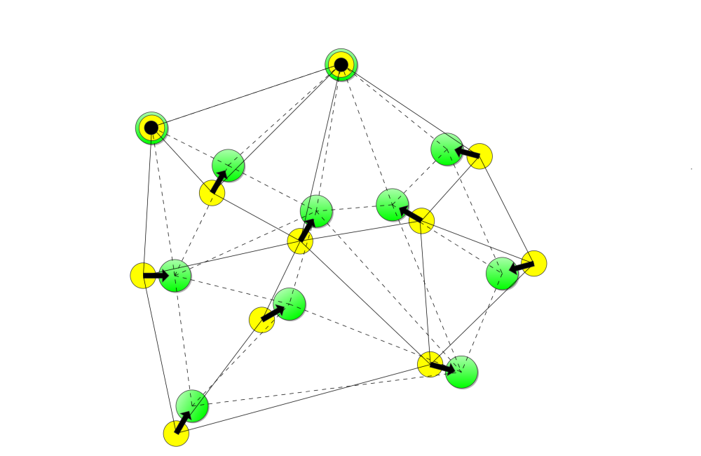
Calculating the shifts
The shifts are calculated by forming two triangulations, one built from the registered shift vector start points (and static points), and one built from the registered shift vector end points (and static points). Then the shifted geometry is calculated by replacing each vertex with its equivalent location, calculated by getting the location in the start triangulation and finding the point in the equivalent triangle in the end triangulation.
Note: For performance, shift field triangulations are created in-memory when a Session runs, and they are not controlled by the normal behaviour of Sessions. To alter the registered input vectors/geometries then you must stop and run the Session again. A paused Session will not be able to resume on a different or restarted engine, you will need to restart the whole Session.
Shift the Data
The process of shifting the data can be broken down into three sub-steps:
-
Register the known shifts
-
(optional) Record any geometric constraints
-
Apply the shift vectors to the data
Register the Known Shifts
The aim of this stage is to build a shift field, based on known shifts in the data (shift vectors and points).
This field is built using multiple calls to the 1Integrate built-in operation register_shift_vector, which registers a single shift. This built-in operation requires two parameters:
-
The name of the shift field.
This name must be the same for all shifts registered in the field. It will also be used later on to apply the shifts.
-
A geometry to describe the shift.
This can be either a line with two points (a vector indicated by a start point and an end point), or a point (indicating a location where no shift has occurred)
The higher the density of shift vectors, the more accurate the shifting will be. However, the appropriate balance between data collection costs and the accuracy of the result needs to be worked out for each specific case.
Note: It is essential to record both shift and no-shift information. If no-shift locations are not recorded, then features around these locations will get moved based on the surrounding recorded shifts. The no-shift information will tend to keep nearby features close to their original position.
Record Geometric Constraints
When shifting data, any shared vertices between features will be shifted to the same location, keeping data connected.
Some data does not add vertices where features touch (e.g. branch pipes touch a mains pipe without adding a vertex to the mains pipe). In these situations there are two options:
-
In a separate 1Integrate Session: load the data, build topology and then commit the features to be shifted. This will add new vertices where the features intersect (this may not be acceptable for some data models).
-
Identify ‘master’ features (e.g. the mains pipes) as constraining geometries, which attempts to keep features connected to the master features without adding new vertices.
If option B is required then this can be performed in an Action run in the same Session, after all the shift vectors have been registered, to register these master features as constraining geometries. This has the effect of adding shifting Rules to make sure that any point on a constraining line should remain on (or very close) to that same line after shifting.
Note: Absolute connectivity cannot be guaranteed in this case, so we recommended adding an Action afterwards to fix small errors.
Adding a constraining geometry to a shift field is performed using the built-in operation register_constraining_geometry. This built in operation requires two parameters:
-
The name of the shift field.
This name must be the same as the one used to register shifts in the field.
-
The constraining geometry.
Note: Adding constraining geometries to the process may take some time, so for performance reasons it is recommended to apply as few constraining geometries as possible.
Note: Constraints that cross or touch other constraints will raise an error and not be registered unless there is a common vertex at the cross/touch point.
Apply Shift Vectors
Once a shift field has been populated with shift vectors and any constraining geometries, the shift field can be used to shift other data.
This is performed using the built-in function shift_geometry. This built-in function requires two parameters:
-
The name of the shift field.
This name must be the same as the one used to register shifts and any constraining geometries.
-
The geometry to be shifted.
The result is the shifted geometry that can either be used to replace the old geometry, or to create a new feature as a copy of the original (e.g. using new target classes).
Validate the Results
Once the data has been shifted, then standard 1Integrate functionality can be used to ensure that the data has remained connected and valid.
Rules can be written to check that features are connected to the same features as before the shift, and that the relationships to the base features are the same as before.