Snapping
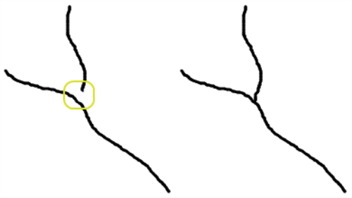
Snapping allows two features to move so that the co-ordinates coincide. When you structure or digitise data, you specify a tolerance where features can be snapped together.

Snapping is an essential prerequisite for determining connections, but is also useful as a general means of maintaining clean data during capture, or cleaning up and aligning features. You can also discover geometry errors, for example spikes, self-intersections, duplicate vertices, and narrow sections in a polygon.
Tolerance
The tolerance, in dataset units, defines how close features must be before snapping takes place. A single tolerance value is used for all classes within a session.
Note: If you do not want your data to move, a tolerance of 0 can be specified. Small amounts of snapping may still occur in order to maintain the correct topology.
You should choose a snapping tolerance for your data based on the quality and the scale of the data.
Data that is very clean can structure with a low tolerance. The tolerance you specify is the amount that you want the data to deviate.
Warning: In general, it is recommended that a large tolerance is not used. A large tolerance increases the chance of a topology engine being unable to structure features because of ambiguous snapping decisions.
Snapping Order
Objects snap to each other in order of processing. The Build Topology Task specifies the order in which to process the classes in the data, with classes later in the list snapping to the classes listed before them.
When an object is snapped in a build topology task or subsequently created or updated by an action, then the object is snapped to the topology primitives created by the previously processed objects.
Snapping Types
Snapping types exist in the network and planar topology models.
The following snapping types exist for the network model:
-
Share nodes
-
Nodes split edges
-
Edges split edges
Note: The planar model uses only the Edges split edges snapping type.
Share Nodes
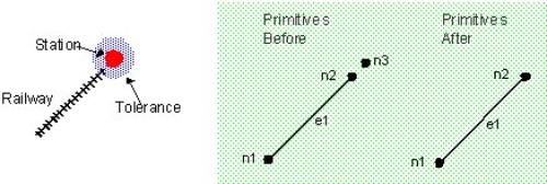
If a node of a newly created or modified geometry is sufficiently close to the node of an existing object, the new geometry is adjusted to share the existing node.
In the example below, a railway line has been added, its end point lying within the tolerance of a station. When a share node tolerance is defined and the station and the end of the line lie within it, these two objects snap together, sharing a single node.

Nodes Split Edges
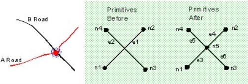
If the node of a newly created or modified geometry is sufficiently close to any part of an existing object, the edge closest to the node is split into two, with a node between the two new edges. The new geometry is adjusted to share this node.
In the example below, the service station is shown as snapping to the road, which does not move. Control over which objects move when snapping takes place is defined by the order of classes.

Conversely, if the edge of a newly created or modified geometry (the A-road) is sufficiently close to the node of an existing object (the B-road), the edge is split in two, and the new geometry is adjusted to share the existing node.

Edges Split Edges
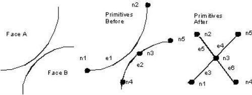
If any part of a structured geometry is sufficiently close to any part of an existing object, the edges closest to the meeting point in both objects are split into two. A node is created between the two new edges in the existing object, and the new geometry is adjusted to share this node.

In the example planar topology model shown below, two faces come close to each other. The node on the edge of Face B is split into 2, and the new geometry is adjusted to share the existing node.
