Topology Types
The topology of a set of geometries can be represented as a linear network topology or as a planar topology.
Network Topology
A network topology uses node and edge primitives to describe interconnected linear features and points on a map or the boundaries of polygons.
-
Edges can represent such features as roads, railways, power lines and rivers.
-
Nodes are used to represent such features as junctions in a transport network, valves in a pipeline, or stops on a bus route.
Network topology is useful for detecting dead ends or unsplit lines. You can create network topology even if your data contains polygons. Structuring is faster in network topology and more accurate. However, some functions such as finding overlaps, voids or polygonising linear data require planar topology.
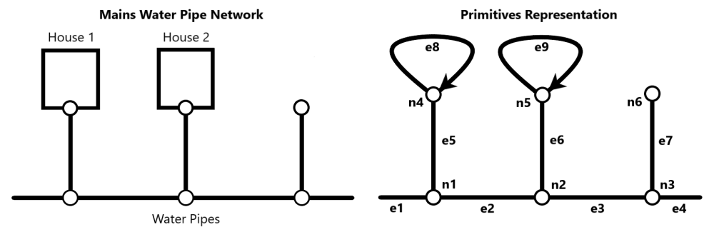
The example below shows a section of a simple water mains pipe network and the corresponding topological representation consisting of nodes and edges. The pipes are represented by the edges between the nodes. The valves are represented by nodes.
Network topology makes it possible to create queries without having to compare geometries at every junction. The topological data enables the information to be obtained by a simple relationship query. The alternative, without the topology model, would be to infer the information from the feature geometry through the less efficient process of multiple direct spatial comparisons.
Planar Topology
Planar topology uses face primitives in addition to nodes and edges to describe two-dimensional areas on a map.
A face is formed within every closed set of edges.
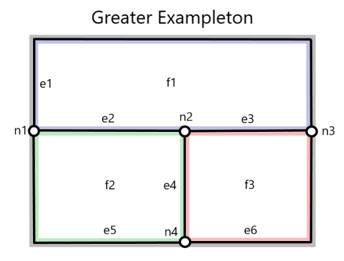
The example below shows how areas in an imaginary land parcel can be described in terms of nodes, edges and faces. The land parcel consists of an area called Greater Exampleton, which contains three administrative areas (Budleigh Exampleton, Old Exampleton, and Little Exampleton).
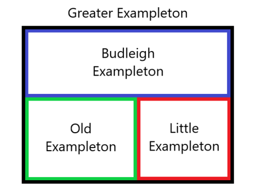
Each administrative area is represented by an individual face, while Greater Exampleton consists of all three faces combined. These are then split by four nodes and six edges.
Describing area topology in terms of faces and boundaries makes it easy to determine the adjacency and containment properties of an area without analysing the geometry of the area.
Another example of the use of planar topology is to answer a query about the fields bounding a particular field. A rapid result can be provided by identifying, through the edges, the faces adjacent to the face primitives of the target field. In contrast, a geometrical evaluation would have to make a spatial search around the target field then, for each object found, make a detailed comparison of the area geometries.
Planar topology is required for the following topology operations:
-
Creating polygons from lines
-
Detecting overlaps between polygons
-
Detecting holes between polygons
-
Splitting polygons


