Using the Create data bar, you can create features in the specified class by digitising a geometry of the required type: a point, line, polygon, or a circle defined by three points on its circumference. You can also:
Click ![]() to select the feature
class you want to use to create data. The most recently used selection
appears at the top of the list.
to select the feature
class you want to use to create data. The most recently used selection
appears at the top of the list.
Click ![]() to pin or unpin the menu to the screen,
keeping it visible when working in the map. Click
to pin or unpin the menu to the screen,
keeping it visible when working in the map. Click ![]() to toggle repeat mode on or off. With repeat mode enabled, as you create
one feature you can immediately create another of the same class and geometry
type without having to select them from this bar again.
to toggle repeat mode on or off. With repeat mode enabled, as you create
one feature you can immediately create another of the same class and geometry
type without having to select them from this bar again.
When you select a geometry type in the Create data bar, you can start digitising and additional options in the Context bar are displayed.
To create a secondary geometry, click on the primary geometry to bring up the feature selection list and click on the unset secondary geometry in the list. This allows you to then digitise the new secondary geometry for the selected feature.
To abandon an operation, click ![]() in the
Context bar.
in the
Context bar.
The following operations are available in the Create data bar:
 |
Use these icons to digitise a point, line,
polygon, or circle. Use |
Remove a defined region of a polygon.
To create a hole:
Select an existing polygon.
Click ![]() and digitise a hole.
and digitise a hole.
Double-click or select ![]() to
confirm your changes. The polygon is removed from the feature and
a hole is created.
to
confirm your changes. The polygon is removed from the feature and
a hole is created.
It is often easier to use another feature to punch a hole in a polygon by selecting the polygon and using the Punch operation.
Create a new feature of a specified class from two or more features that touch or intersect, or create a new feature based on a single feature.
To create a union of features:
Select a feature. If you are creating a union from more than one feature, ensure Multi Select is enabled and select the features. (For more information about selecting multiple features, see Selecting_multiple_features.) Alternatively, use Ctrl+click to multi-select features.
Select a class for the new feature from the Create data bar.
Click ![]()
A new feature with the selected class is created on top of the existing feature(s) and any existing features remain in the layer below.
If you have a class in your data that has
no geometry but is made up of references to other member features, select
the member features, select the class of the group feature, and click
![]() to create the feature. You
can select the group feature by selecting one of the members and navigating
the 'composes' property back to the group feature, or by running a search
on the group class.
to create the feature. You
can select the group feature by selecting one of the members and navigating
the 'composes' property back to the group feature, or by running a search
on the group class.
Add a single point on or in line with an existing line or defined vector. As you add points, the tie out distance (distance remaining to the end point) is automatically calculated and displayed in the panel.
To add a point to a line:
Select the line along which you want to add a point.
Using the Create data bar, select a class for the point.
Click ![]()
Select the end of the line from which distances will be measured.
Enter the distance along the line to place the point and a height for the point. Click Accept.
If the distance specified for the distance is negative, the point is placed on the backward projection of the line’s first segment. If the distance is greater than the length of the line, the point is created on the projection of the line’s last segment.
The point is created at the specified distance along the line.
To add a point on a defined vector:
Using the Create data bar, select a class for the point.
Click the Point along line icon.
Click the map to indicate the start of the vector along which you want to add the point.
Click the map to indicate the end of the vector.
Enter the distance along the vector to place the point and a height for the point. Click Accept.
If the distance specified for the distance is negative, the point is placed on the backward projection of the vector. If the distance is greater than the length of the line, the point is created on the forward projection of the vector.
The point is created at the specified distance along the vector.
Add multiple points relative to a line or defined vector. Points are created at a specified distance along the line or vector at a specified perpendicular offset and height. As you add points, the tie out distance (distance remaining to the end point) is automatically calculated and displayed in the panel.
To add one or more points on a vector:
Select the vector to use as a relative location for the points or digitise a vector.
Select a class for the points.
From the Create data
bar, click ![]() The Chainage and Offset panel is displayed:
The Chainage and Offset panel is displayed:
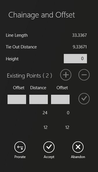
Select the end of the line where you want the series of points to begin.
Enter the height for the first point in the Height field. The last value entered in the Height field can be reused for additional points.
If the number specified for the distance is negative, the point is placed on the backward projection of the line’s first segment. If the distance is greater than the length of the line, the point is created on the projection of the line’s last segment.
Enter a value in the Offset field(s). A value in the left-hand Offset field creates a point to the left of the line, and a value in the right-hand Offset field creates a point to the right of the line.
Enter a distance in the Distance field.
Click ![]() to add the point.
to add the point.
Repeat steps 5-8 to place additional points on the map. The most recent point added is displayed at the bottom of the list.
To edit an existing point, select it from the list then enter new values.
To continue adding new points
after editing an existing point, click ![]()
To finish adding points, click Accept or to discard your changes or click Abandon to cancel the operation.
Prorating allows you to match calculations taken on the ground to the map, compensating for any differences in calculations.
To prorate distances:
Enter the distance to the end of the line as measured on the ground in the Observed Tie Out Distance field.
In the Tolerance Warning field, enter the distance a point can deviate from the map point before a warning is displayed.
Click Preview. If no warnings are displayed, the map is updated to show the new distances. Click Accept to confirm changes or Cancel to abandon changes.
Create points at defined intervals along an existing line or a user-specified vector. If a line is already selected, it will use this line. Otherwise, the start and end of the vector must be specified.
To add points to a line:
Select the line along which you want to create points.
Using the Create data bar, select a class for the point.
Click ![]()
Click on the map to indicate the start of the line, where the series of points will begin.
Enter the distance between intervals and a height for the points. Click Accept.
Points are created, starting at 0, at each interval along the length of the line or arc.
To add points on a defined vector when there is no existing line:
Using the Create data bar, select a class for the point.
Click ![]()
Click on the map to indicate the start of the vector, where the series of points will begin.
Click on the map to indicate the end of the vector.
Enter the distance between intervals and a height for the points. Click Accept.
Points are created, starting at 0, at each interval along the length of the vector.
Points are created relative to a baseline using distance and bearing.
To add one or more points on a vector:
Using the Create data bar, select a class for the point.
Click ![]() and select one of the following options: Create Points, Create Lines,
or Create Polygon.
and select one of the following options: Create Points, Create Lines,
or Create Polygon.
Digitise the baseline. The Manual Traverse panel is displayed.
Select Distance & Bearing to set the angle of deviation and distance or Relative Distance to enter an offset and distance in meters.
To add more entries, click ![]() To delete an entry, select it and click
To delete an entry, select it and click ![]()
To adjust the baseline click Redefine Baseline, then click Continue and redigitise the baseline.
Click ![]() to accept any changes.
to accept any changes.