
Connecting Network Graphs
Network graph connectivity is defined by setting up an action using built-in operations (see Network Graph Connectivity Operations).
A network graph is defined in two parts, which must be performed in order using a sequence:
-
Define the objects within the network graph (using theadd_position and remove_position built-in operations)
-
Set up the connections within the network graph (using theconnect_positions and disconnect_positions built-in operations)
Note: You can add and connect features which already exist in the network graph, but an error occurs if you try to connect or disconnect features which have not yet been added. If you remove a feature from the network graph, you do not need to disconnect it first.
Spatial relationships are used to define how the points and lines interact (e.g. touch, overlap, or cross). In a network graph constructed from point and line features, the points become nodes and the lines are the connections between the nodes.
You can construct multiple network graphs in 1Integrate. Although rules are run against all network graphs, each is reported separately.
Note: Contexts allow you to select the network class and attributes in a rule or action (see Context).
Actions can be created in many ways to achieve the same network graph connectivity. Labels and multiple actions can be used to connect a network graph in stages.
- See Example: One-way Road Networkfor an example of a network graph that can be constructed using two methods.
- See Example: Transport Networkfor an example of a network graph constructed in stages.
Line Networks
In the example below, the points of contact become nodes in the network graph, with road sections as the connections.
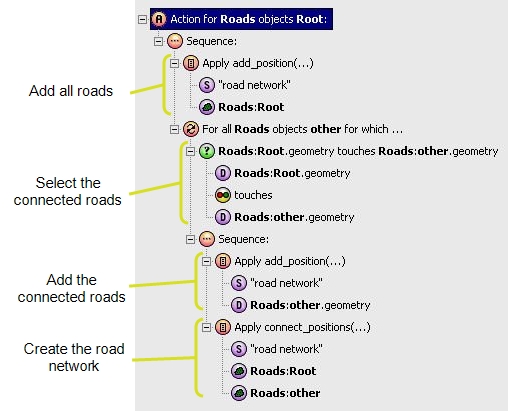
Example action defining a simple road network
Line and Point Networks
The following example shows how a network graph of valves (points) and pipes (lines) might be defined.
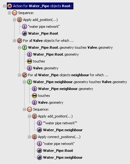
Example action defining a network of valves and pipes

Copyright © 2017 1Spatial

