Survey Device settings are accessed from the Settings menu in the Charms bar (see Charms Bar).
-
Open the Charms Menu and select Settings > Survey Devices.
-
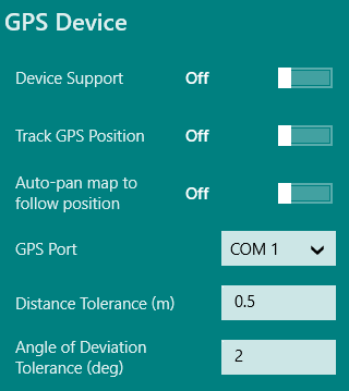
Under GPS Device, toggle GPS Support to On.
-
(optional) To track your current GPS position whether or not you are capturing points with your
device, toggle Track GPS Position to On.
-
(optional) To automatically centre the map to your current position when using manual or continuous
GPS capture, toggle Auto-pan map to follow position to On.
-
In the GPS Port list, select the COM port to which your device is connected.
-
In the Distance Tolerance field, enter a distance in dataset units.
This is used to define the minimum distance between captured points when doing continuous
capture (see Continuous Capture).
-
In the Angle of Deviation Tolerance field, enter an amount (in degrees) to control
how far to deviate from a straight line before a new point is captured. This prevents lots of redundant points along a straight line being captured.
Set
this value to 0 if you want to capture all points.
-
In the GPS Quality Levels area, you can configure the ranges of values for coordinate
quality levels.
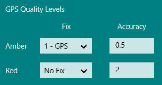
This determines if an amber or red quality level is shown, when either the Accuracy or
the Fix drop to the amber or red thresholds.
- In the Fix drop-down lists, select No fix value, 1-GPS, 2-DGPS, or 3-HPN for both
the Amber and Red fields. These values are inclusive, so when the fix drops to the
specified level, the warning is displayed.
- In the Accuracy fields, enter values (in meters) for both Amber and Red.
-
Click the back arrow to close the menu and save your settings.
-
Open the lower app bar and select Devices > GPS.
The GPS Status panel is displayed.
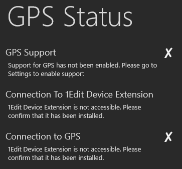
Refer to any messages in this panel to resolve any issues.
-
Open the Charms Menu and select Settings > Survey Devices.
-
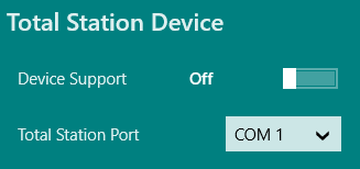
Under Total Station Device, toggle Device Support to On.
-
In the Total Station Port list, select the COM port to which your device is connected.
-
Click the back arrow to close the menu and save your settings.
-
Open the lower app bar and select Devices > Total Station.
The Total Station Status panel is displayed.
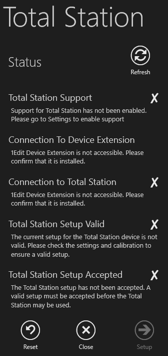
1Edit checks whether or not Total Station support has been enabled, tests the connection
to Total Station, and whether or not the Total Station setup is valid and accepted.
Each status check is followed by a tick or cross, and contains information about
any potential issues.
-
Click Reset to clear any previously stored settings and calibrations.
-
Click Setup.
The Instrument Details page is displayed.
-
Enter the height of the Total Station (required) and the default height of the prism
(if applicable).
-
Click Stations.
The Station Selection page is displayed.
-
To indicate the location of the control station (the Total Station), click Pick Control
and select a feature such as a point or vertex on the map.
-
To nominate a feature on the map as the reference station, click Pick Reference and then
select the feature.
-
To carry out further error checking of the Total Station configuration, click Pick Check
and select a point or vertex on the map to represent the check station.
After you select each station, a construction point is placed at the location indicated,
and each point is given a name that can be modified. The height of the selected map
feature associated with the station is also displayed.
If you want to use the height
value of the station for calibration, tick the Height box. If a height is not selected,
any observations captured from the Total Station will be assigned the current digitising
height.
-
Click Calibration.
This page initially shows the 2D distance from the control station
location on the map to the reference and check stations on the map.
-
Target the Total Station at the reference object. Click Observe Reference to take
a Total Station observation. Repeat this step for the check station if one has been
nominated.
After each observation the observed 2D distance, the distance is displayed and the
difference between the map and observed distances.
For the reference observation,
the horizontal angle of the device is displayed. For the observation check, the observation
error is displayed, which is the 2D distance between the location of the check station
on the map and the computed location of the check station.
-
Tick Apply differential error to observations to apply the differential error between
the map locations and observed locations to observations taken for this Total Station
setup.
-
Click Accept to use the calibrated setup for any observations captured.